


 Sodium hypochlorite solution, generated in the electrolyzer, flows to the (working) sodium hypochlorite tank, from which, through the automatic dosing system is injected in treated water.
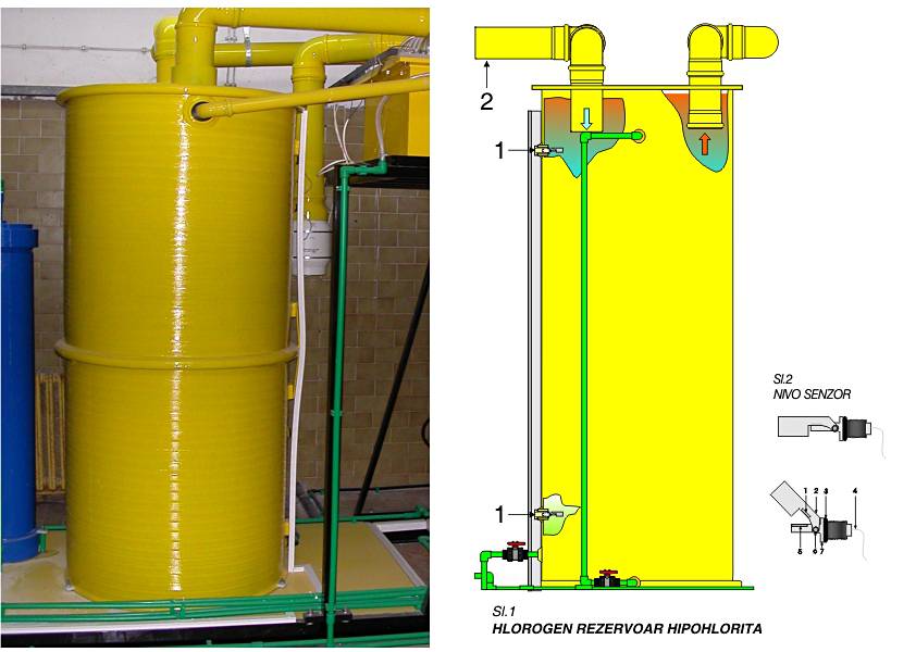
Tank has two level indicators, which are connected to Hlorogen PLC. Those two level indicators are the maximum level indicator and the minimum level indicator. When a hypochlorite level reaches the maximum level in the tank the electrolytic process is stoped, and when a hypochlorite level fall to the minimum level, the electrolytic process is continued.
The working autonomy on maximum consumption of the sodium hypochlorite is 3.5 days. The autonomy can be extended with adding one or more extension tanks.
Fig.1 HLOROGEN SODIUM HYPOCHLORITE TANK Components: 1. Sensor max. hypochlorite, 2. Sensor min. hypochlorite, 3. ventilation system
Fig.2 LEVEL SENSOR – Components: 1. contact with the float, 2. float 3. o-ring, 4. cable 2×0.50mm, 5. contact on the body of level sensor 6. float axis, 7. body of level sensor